⚡ Week 9: Input Devices
FAB ACADEMY | XIAO ESP32-C3 | STEMMAQT SENSOR | LOGIC ANALYZER
01 — Overview & Learning Goals
This week's assignment focuses on input devices — sensors and components that feed real-world data into a microcontroller. The goal is to design or use a PCB with a microcontroller, connect an input sensor, measure its output signals, and understand the communication protocol at the electrical level. In this week's group assignment, Aleksi instructed us on how to measure I²C signals using a small time-of-flight rangefinder module, a potentiometer, a light sensor, and a thermistor. It was nice to see how easy it is to integrate these sensors into a device.
🎯 Group Assignment
Probe an input device's analog levels and digital signals using a multimeter and oscilloscope/logic analyzer, and document the measurements.
🎯 Individual Assignment
Measure something — add a sensor to a microcontroller board and read it. Document your design, code, and observations.
🔧 My Setup
Custom PCB with XIAO ESP32-C3 + StemmaQT IMU sensor over I²C, signals captured with a Logic Analyzer.
💡 KEY CONCEPT
Input devices convert physical phenomena (temperature, acceleration, light, distance…) into electrical signals a microcontroller can read. Understanding the protocol — analog voltage, I²C, SPI, UART — is just as important as reading the value itself.
02 — Hardware: Custom PCB + XIAO ESP32-C3
My custom PCB was designed in KiCad and milled at the Fab Lab. It hosts a Seeed Studio XIAO ESP32-C3 as the main processing unit, with castellated mounting pads, To maximize prototyping flexibility, all GPIO, power, and ground pins are broken out to both male and female headers.
XIAO ESP32-C3 Key Specs
| Parameter | Value |
|---|---|
| MCU | ESP32-C3 (RISC-V 32-bit, 160 MHz) |
| Flash | 4 MB |
| SRAM | 400 KB |
| I/O Voltage | 3.3 V |
| Connectivity | Wi-Fi 2.4 GHz, Bluetooth 5.0 LE |
| I²C Pins | SDA → GPIO6, SCL → GPIO7 |
| SPI Pins | MOSI → GPIO10, MISO → GPIO9, SCK → GPIO8, CS → GPIO20 |
| ADC | 12-bit, channels on GPIO2, GPIO3, GPIO4 |
| USB | USB-C (native USB Serial, CDC) |
| Operating Voltage | 3.3 V / 5 V tolerant input |
 (1).jpg)
03 — StemmaQT Sensor
The LSM6DS33 is a 6-axis inertial measurement unit (IMU) that contains both a 3-axis accelerometer and a 3-axis gyroscope. The accelerometer measures linear acceleration along the X, Y, and Z axes, while the gyroscope measures angular velocity along the same axes. These measurements can be used to detect motion, orientation, and tilt of the device. My plan is to measure the sensor's output signals using a logic analyzer and a write a sketch to read the imu values and convert the acceleometer readings into angles.
.jpg)
The sensor communicates with the microcontroller using the I²C (Inter-Integrated Circuit) protocol. Through this interface the microcontroller can read acceleration and rotational data from the sensor registers and process it for applications such as motion tracking or tilt angle estimation.
What is I²C?
I²C uses only two wires: SDA (Serial Data) and SCL (Serial Clock). It's a multi-device bus — multiple sensors can share the same two pins, each addressed by a unique 7-bit address. Communication is always initiated by the master (here: the XIAO ESP32-C3).
📡 Protocol
I²C
Two-wire: SDA + SCL
Speed: 100 kHz (Standard) / 400 kHz (Fast Mode)
🏠 Addressing
7-bit address space (128 possible devices). Most StemmaQT sensors have a default address and allow 1–2 address pins to change it.
🔗 Daisy Chaining
StemmaQT boards have two connectors — you can chain multiple sensors on the same bus without a breadboard.
I²C Transaction — How It Works
Every I²C transaction follows this sequence. Understanding this is critical for interpreting logic analyzer captures:
🟣 START Condition
SDA falls while SCL is HIGH. This is the handshake that tells all devices on the bus a transmission is beginning.
🟡 Address + R/W
7 bits of device address followed by 1 Read/Write bit. Data is sampled on the rising edge of SCL.
🟣 ACK / NACK
After each byte, the receiver pulls SDA LOW (ACK) or leaves it HIGH (NACK) to confirm receipt.
🟣 STOP Condition
SDA rises while SCL is HIGH. Signals end of transmission; bus returns to idle.
04 — Wiring & I²C Connection
Since I am not using the jst connector, I will be using the direct pin connections. The only hurdle here is ensuring the correct pin assignments for SDA and SCL. On my board the pin D4(GPIO6) Which connects to SDA is part of female connectors while D5(GPIO7) which connects to SCL is part of male connectors so I had to use different jumper cables to wire them.
This is what it looks like on the board:
.jpg)
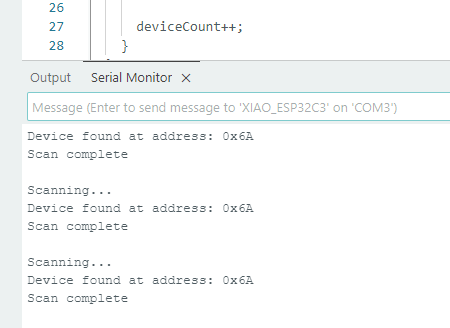
Testing the I²C Connection with an I²C Scanner
I first uploaded a simple I²C scanner sketch which I got from Chatgpt to the XIAO ESP32-C3 to verify that the sensor is properly connected and responding on the bus. This code scans all possible I²C addresses and prints any devices it finds to the Serial Monitor.
#include <Wire.h>
void setup() {
  Wire.begin();           // Start I2C
  Serial.begin(115200);   // Start serial communication
  while (!Serial);        // Wait for serial monitor

  Serial.println("\nI2C Scanner");
}

void loop() {
  byte error, address;
  int deviceCount = 0;

  Serial.println("Scanning...");

  for(address = 1; address < 127; address++) {

    Wire.beginTransmission(address);
    error = Wire.endTransmission();

    if (error == 0) {
      Serial.print("Device found at address: 0x");
      if (address < 16)
        Serial.print("0");
      Serial.println(address, HEX);

      deviceCount++;
    }
  }

  if (deviceCount == 0) {
    Serial.println("No I2C devices found\n");
  } else {
    Serial.println("Scan complete\n");
  }

  delay(5000); // Wait 5 seconds before scanning again
}
The code ran sucessfully and it gave the address of the sensor 0x6A, confirming the wiring was correct..
05 — Programming the Sensor
First I downloaded the appropriate library for the LSM6DS33 sensor from library manager which was the Adafruit LSM6DS library. Then I used the example code provided by the library to read the accelerometer and gyroscope data from the sensor which can be found from File → Examples → Adafruit LSM6DS → adafruit_lsm6ds33_test. I changed the delay from 100ms to 2000ms so its easier to see the data change on the serial monitor. This is what the values lookled like as I moved the sensor:
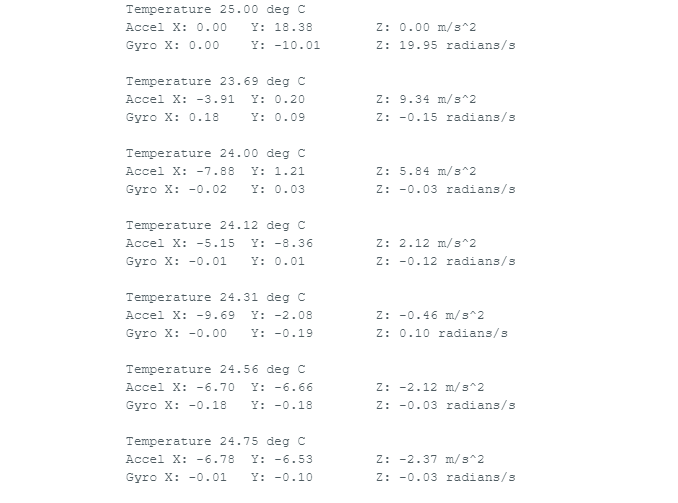
As you can see, the values change as I move the sensor.
Now since I wanted to read the angles of the board, I had to convert the accelerometer readings into angles. The accelerometer gives us the acceleration values along the X, Y, and Z axes.
The tilt angle is calculated using the arctangent function. This function determines the angle between components of the acceleration
vector. In the code, the atan2() function is used because it handles both positive and negative values correctly and
returns the angle in the correct quadrant.
For example, the pitch angle can be calculated from the accelerometer values using the following relationship:
θ = arctan( x / √(y² + z²) )
In this equation, x, y, and z represent the acceleration values measured along each axis.
The result of the arctangent calculation is returned in radians. To convert the value into degrees, the result is multiplied by
180 / π.
As the board is tilted, the acceleration values change and the calculated angle updates accordingly. This allows the orientation of the sensor to be observed in real time through the serial monitor.
The following is the code used for calculating the tilt angles which keeps the basic code from the example and adds the angle calculations which I coded myself:
#include <Wire.h>
#include <Adafruit_Sensor.h>
#include <Adafruit_LSM6DS33.h>
Adafruit_LSM6DS33 lsm6ds;
void setup() {
  Serial.begin(115200);
  while (!Serial);

  if (!lsm6ds.begin_I2C()) {
    Serial.println("LSM6DS33 not found");
    while (1);
  }

  Serial.println("LSM6DS33 ready");
}

void loop() {

  sensors_event_t accel;
  sensors_event_t gyro;
  sensors_event_t temp;

  lsm6ds.getEvent(&accel, &gyro, &temp);

  float ax = accel.acceleration.x;
  float ay = accel.acceleration.y;
  float az = accel.acceleration.z;

  // Calculate roll and pitch
  float roll  = atan2(ay, az) * 180.0 / PI;
  float pitch = atan2(-ax, sqrt(ay * ay + az * az)) * 180.0 / PI;

  Serial.print("Roll: ");
  Serial.print(roll);
  Serial.print("   Pitch: ");
  Serial.println(pitch);

  delay(1500);
}
This is what it looked like as the board was moved around:
06 — Measuring Signals with a Logic Analyzer
A logic analyzer captures and displays digital signals over time, letting you see the exact I²C transactions happening between the XIAO ESP32-C3 and the sensor. This goes far beyond what a multimeter can show — you can decode every byte of data being exchanged.
What is a Logic Analyzer?
Unlike an oscilloscope (which shows analog voltage waveforms), a logic analyzer samples signals at high frequency and records them as binary (HIGH/LOW). Modern USB logic analyzers like the Saleae Logic 8 or the affordable 8-channel 24 MHz clone (often labeled "USB Logic Analyzer") work with open-source software like PulseView / sigrok.
🔬 Saleae Logic 8
Professional-grade. Up to 100 MHz digital, 50 MHz analog. Uses Logic 2 software with built-in I²C, SPI, UART decoders. Pricey but excellent.
💰 Budget Clone (8ch 24 MHz)
~$10 USB analyzer. Works with PulseView (sigrok). Sufficient for I²C at 400 kHz. Use a shielded USB cable to reduce noise.
💻 PulseView / Logic 2
Free, open-source, cross-platform. Supports hundreds of analyzers. Has built-in I²C protocol decoder — shows address, data bytes, ACK/NACK in plain text.
Step-by-Step: Capturing I²C with the Logic Analyzer
I went to sigrok.org to download PulseView but for some reason the website was not loading properly so I couldn't download it. Therefore, I ended up downloading Logic 2 from the Saleae website.
When you connect the logic analyzer to the computer and open the logic 2 software, it automatically detects the device and brings up the main interface.
.png)
Connect the Probes
Attach the logic analyzer probes to the test points on your PCB. You need at minimum:
CH0 → SCL (GPIO7 test pad)/D5
CH1 → SDA (GPIO6 test pad)D4
GND → GND pad
Configure Logic 2
Set it to analyze and select i2c.
Add the I²C Protocol Decoder
In Logic 2: assign CH0 to SCL, CH1 to SDA. The decoder will automatically annotate every START, address byte, data byte, ACK, and STOP condition above the waveform.
Trigger & Capture
Press Run in your software, and have the arduino sketch running in the background. Stop capture after a few reads. You should see bursts of I²C activity separated by the 1-second delay.
I also used an oscilloscope to see what the i2c singal looks like as in the Fab Lab here we have a logic analyzer attachment. It was fun to use but I had to ask Antti for help since I am not that great at oscilloscopes.
.jpg)
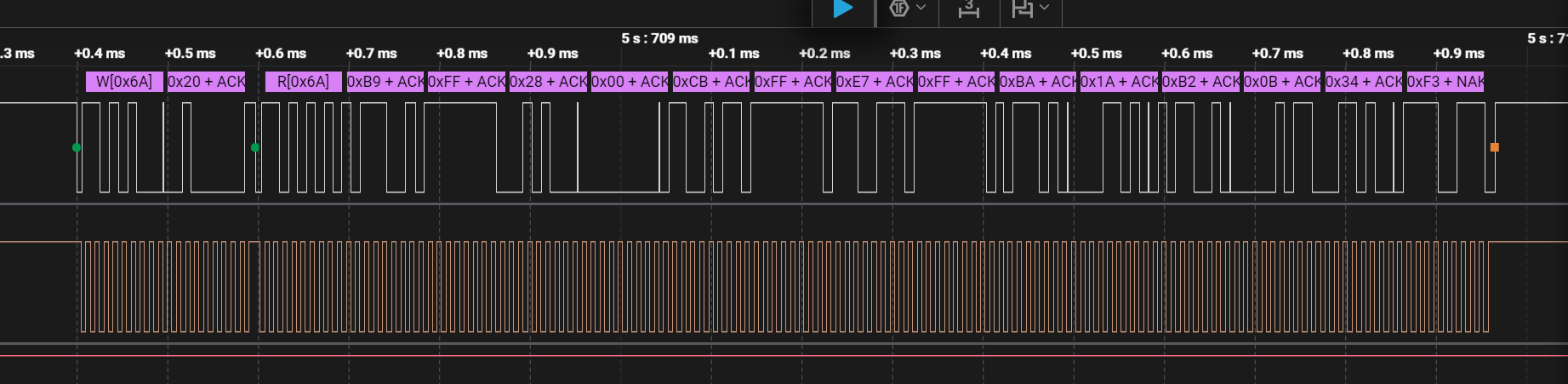
- Bus Idle State: The I²C bus idles HIGH, confirming that the SDA (D0) and SCL (D1) lines are correctly pulled up to the 3.3V logic level, as indicated by the high state before the start condition.
- Transaction Protocol: Each communication cycle consists of a Write transaction to address
0x6Ato set the register pointer (0x20), followed by a Read transaction to retrieve a continuous stream of raw sensor data. - Data Payload: The sensor provides a large multi-byte burst (visible as 15+ bytes in the capture, including
0xC8,0xFF, and0x26). This payload contains the 16-bit raw values for the accelerometer and gyroscope axes. - Hardware Handshaking: The Logic 2 decoder confirms a valid ACK (indicated by the green dots) after the address
0x6A, proving the LSM6DS sensor is correctly powered and addressing is successful. - Signal Timing: The clock frequency (SCL) is measured at 50 kHz with a pulse width of 10.25 µs. This is a conservative, stable speed well-suited for the jumper wire connections used in this setup.
- Protocol Integrity: The SDA line (D0) transitions occur correctly during the LOW phase of the SCL (D1), and the final NAK (red square) at the end of the sequence confirms the XIAO has successfully signaled the end of the read operation.
In general I had fun in this week since I actually got to learn more about the i2c protocol and got to see the signals using logic analyzerz. Moreover, I thought two of the pins were not working so I used a multimeter to check the connections using a simple blink script and they were alright.
 ← Back to Main Page